Now you can order your parts from Alert and fit them yourself, following the advice and full set of instructions on how to perform many typical DIY tasks on the links below.

Definitions and Explanations

Replace the timing chain when:

  • Always refer to manufacturers specifications and recommendations.
  • The tensioned plunger projection exceeds 10mm for OHV engines and 12mm for OHC/DOHC engines.
  • Stiff chain articulation is experienced.
  • Abnormal wear is visible on the bushings, rollers or link plates of the chain.
  • When the maximum length measured, over 16 pitches (i.e. pitch = distance from pin to pin), in any three places over the length of the chain exceeds the maximum allowed. Refer to the manufacturers specifications for your make of vehicle.

Replace the chain tensioner when:

  • Heavy indentations or scratch marks, deeper than 0.5mm, appear on the surface of the rubber pad.
  • Peeling of the rubber pad from the steel shoe of the tensioner plunger is evident.
  • Abnormal wear is observed on the plunger tube.
  • The ratchet system has failed.

Replace the chain guide rail when:

  • Heavy indentations or scratch marks, deeper than 0.5mm, appear on the surface of the rubber pad or guide rail.
  • Peeling of the rubber from the steel pressing has occurred.

Replace the sprockets when:

  • They are excessively worn.
  • Scratches, indentations or chips are visible on the sprocket teeth. Uneven wear is evident at the root of the sprocket teeth.

Pistons are very specialised parts in an engine. Because the forces put on them are extreme at the time of combustion, they need to be manufactured to exact tolerances and handled correctly. A little-known fact is that a piston, when cold, is not round but oval. A piston reaches its operating dimensions within approximately 130 seconds after starting the engine. The combustion temperature in a non-turbo engine reaches ±13000ºC at the time of combustion and a turbo charged engine‘s combustion temperature is almost double that. Up to 60% of this temperature is transmitted to the top compression ring and then into the bore wall and then into the coolant water. Added to this, the pressure exerted on the piston crown at the same time is (and must be) high enough to propel your car! These very same pressures and temperatures are exerted on the cylinder head gasket “culot” (the metal ring around the bores in the gasket). Pistons can change in many ways depending on the application in which they are used. Pistons also have a correct direction in which they must face in an engine. They have a “front” and a “back”. An arrow, or sometimes a dimple, on the crown will indicate the front. If you turn a piston upside down you will note that the gudgeon pin is offset from centre.

Some Definitions

  1. Gudgeon pin – This is the pin that goes through the piston and connects the piston to the connecting rod.
  2. Piston skirt – This is the bottom of the piston. It is at this point, in the opposite direction of the gudgeon pin, that a piston is measured (if the gudgeon is north/south, you measure east/west).
  3. Crown – Is the top of the piston.
  4. Gudgeon pin eye – This is the hole in the piston through which the gudgeon pin travels.
  5. Connecting rod eye – This is the hole at the top of the connecting rod through which the gudgeon goes.
  6. Small end bush – This is the brass bush fitted into the gudgeon pin eye on the connecting rod.
  7. Clearance – This is the difference between the bore size and the piston size. For example: bore size 84.00mm piston size 83.96mm = clearance of .04mm, or what is commonly known as the “SP” number. This reference is sometimes stamped on the piston crown.
  8. Compression height – This measurement is the distance between the piston crown and the middle of the gudgeon pin.
    Length – This is the measurement between the crown and the bottom of the skirt (total length).
  9. Bore – This is the standard bore size of the engine. Most engines can be “re-bored” by an automotive engineer. Typically the first oversize will be 0.50mm (0.020”). The next being 1.00mm (0.040”). Obviously the bore increases by these amounts.
  10. Stroke – This is the measurement between the centres of the gudgeon pin and the centre of the connecting rod journal on the crankshaft.

There are some very technical details to bear in mind when dealing with a bearing “shell”. Besides the different materials that are used, there are some very important procedures that need to be considered when fitting new bearings. These revolve largely around a bearing’s dimensions. Here are some interesting facts that apply to big end or main bearings, irrespective of whether your engine is petrol or diesel.

  • A bearing shell – you’ll notice as you take it out of the packet – is not a perfect half round. The ends are slightly spread. This is so that when you
    put it into its housing, it will need some pressure from your thumbs to get it in. This pressure, exerted by your thumbs, is called the “nip”.
  • Believe it or not, the shell is also very slightly longer than the housing it is going into. This is because the shell, when clamped onto the crankshaft journal, has to be perfectly round and the only way this can be done is by pushing the ends of the shell down, when you “torque” up the bolts or nuts”. This is known as “Bearing Crush”.
  • There is a cut-away at the one end of the shell, which is known as the “keep”. This goes into a groove in the housing, to stop the shell moving sideways
    out of its housing during assembly and when the engine is turning.
  • Remember that there is a specification for what is known as “bearing clearance”. This is the space between the bearing and the crankshaft journal.
    Typically this clearance is small ±0.05mm (0.002”). It MUST be there.

When a crankshaft journal is damaged for whatever reason, the journal needs to be “ground”. This means that the motor engineer will have to grind the journal, in a special machine, in order to take away the damage. Bearings are made in what are called “under sizes” for this reason. The shell is made thicker by the amount that the engineer has made the journal smaller. These under sizes are 0.25mm (0.010”); 0.50mm (0.020”); 0.75mm (0.030”) and 1.00mm (0.040”). If your crankshaft has never been ground and there is no damage to it, the motor engineer will “polish” it and you will use standard, not under size bearings.

Bearing Manufacturers purposely do things to a bearing in order to make things easier for you, to fit their bearings. Let’s deal with the big end, or con rod bearing, first. The terminology “big end” is a simple one. Obviously there are 2 ends to a connecting rod. The smaller hole at the top, into which the gudgeon pin goes, is the “small end” and at the bottom is a bigger hole that is cut in two, which is known as the “big end”. It is in the latter that the big end bearing is fitted. When you open your packet of big ends you will notice the following:

  1. A set of big end bearings consists of twice as many shells as the amount of big end journal on the crankshaft –(ie) 4x big end journals = 8x bearing shells.
  2. Some are of the same colour – (bright & shiny) meaning these are common bearings for upper and / or lower installation.
  3. Some have different shades – (dull grey) “Sputter” bearing shell/s to be fitted in the conrod half of the big end housing – (Shiny bearing shells)
    to be fitted to the cap half of the conrod housing.
  4. Some will have grooves / drilled holes and some will be plain to be fitted upper and lower housings.
  5. Irrespective of whether there is an oil groove or not, you will, in most cases, find that there will be a hole drilled into at least half of the bearing shells.

If you look into the inside of the con rod side of the bearing housing, you will find a small hole drilled up into the con rod. There will be no hole in the “cap”. Now whatever type of bearing shells you have in your packet, there is a simple rule. Always put the shell with a hole (this applies to whether the shell is grooved or plain) into the con rod housing, not the cap … If all the shells are plain and drilled or grooved and drilled, then the manufacturer has, cleverly, made it impossible for you to go wrong!

In the case of main bearings, there are a few things that are quite different from big end bearings. The main bearings are fitted into housings in the cylinder block and are made more robust than big ends. The main bearings carry quite a bit more pressure than the con rod bearings. Added to which in “V” (V6 and V8) type engines, there are fewer main bearings than there are big end bearings. Although the same rule applies as far as grooved shells and under sizes are concerned, there are times when you need to have your wits about you.

One particular example is the main bearing set for the Golf /Jetta range of engines. These engines have 5 main housings or 10 shells. The fixed thrust shell fits into the No. 3 housing in the block. Now comes the break from the norm. There are 5 grooved and 3 plain shells left over!! Four of the grooved shells go into the remaining housings (1; 2; 4 & 5) in the block and one grooved shell goes into the No. 4 cap. The plain shells go into No’s 1; 2 and 5 caps. Generally, when there is a break from the norm like this, the bearing manufacturer will put an explanatory pamphlet into the box. The only bearing shell that has a particular terminology in the main bearing set is the “thrust” shells. In some engines there are loose thrusts, called “thrust washers”. These are always supplied as a separate set. One, two or sometimes four half moon- type spacers go into the side of the centre main bearing housing. Most of the later engines have what are called “fixed thrusts”. This is a shell that is made in a “U” shape. This fixed thrust shell is contained in all the main bearing sets we supply (petrol or diesel). You don’t buy them separately.

The thrust bearing carries the axial load of the crankshaft forward when you depress the clutch. The crankshaft has a specific measurement for this called “end float”. Too much or too little end float will cause damage to the thrust faces and the crankshaft “web” that the thrust face runs against. A particular point to bear in mind is that as the undersize of the main bearing journal changes, so does the width of the fixed thrust. This fixed thrust width does vary from one engine to another. So it is imperative that if your main bearing journals are going to be ground, you must give the replacement fixed thrust shells to your motor engineer.

There are times when an engine will miss-fire, use excessive oil, overheat or be just plain unhealthy, when all that needs to be done is to overhaul the cylinder head. It is here that most D.I.Y. people go wrong. We will deal with this under 4 headings:

• Valves, Guides and Springs
• Head Gaskets
• Thermostats
• Hydraulic Cam Followers

Valves, Guides and Springs

It is commonplace to have a number of configurations of valves in four cylinder engines. 8 valve (4 exhaust and 4 inlet valves); 12 valve (4 exhaust and 8 inlet valves); 16 valve (8 exhaust and 8 inlet valves) and sometimes 20 valve (8 exhaust and 12 inlet valves). The basic overhaul procedures stay very much the same. The only problem that arises is the amount of space available, particularly in multi-valve engines, for them to operate in. The basic premise is to replace worn or burnt valves, warn guides and ineffective stem seals. To ensure that a valve seals the combustion gasses properly, you either need some very sophisticated equipment or really know what you are doing. By this we are not saying that from a D.I.Y. point of view this cannot be done, but that unless it is done correctly the problem won’t be solved. The following areas need to be checked and measured:

  • Valve stem wear
  • Cotter groove wear
  • Guide bore wear
  • Configuration of the entire valve train
  • Valve seats

Valve stems do wear without the valve head burning. This is caused mainly by lack of regular maintenance and foreign matter in the oil. If the clearance between the valve stem and the guide is too big then oil will seep through into the combustion chamber and cause the engine to “smoke” and use oil. Irrespective of whether the seals are new or not. Cotter groove wear can be very dangerous. If a cotter comes off, there is nothing to stop the valve from dropping onto the top of a rapidly rising piston. Very expensive damage can occur. Guides are made to be sacrificial. In other words they are meant to wear, not the valve stem. They often wear oval. This is because the tappet is pushing it down sideways instead of straight down. This is one of the reasons that the entire valve train configuration should be checked.

But why should this change, you ask? Generally speaking, a head is only overhauled because 1) the engine has been over heated; 2) there is lack of compression on one or more cylinders and 3) the engine is smoking and using oil.

There are many cases when, in fact, the first has caused the other two!! They are not necessarily independent of one another, particularly in overhead camshaft (OHC) engines. Picture the scene – OHC heads are generally made of aluminum and camshafts are made of cast iron. Expansion rates cannot be the same. All the parts consisting of the valve drive train are situated and fixed to the head except the overhead camshaft, which runs in what are known as “saddles”. The camshaft won’t bend. The head will. Miss-alignment then occurs. Valves are not pushed straight down, causing the seals to distort and the guides to wear oval; and because the valves are not seating properly, they burn. The re-alignment of the valve train has to be checked and rectified with special machinery, before any valve, guides, etc. are replaced.

Valve springs are generally overlooked when cylinder heads are overhauled. Did you know that in the design of the valve train, manufacturer’s engineers have specifications for the speed in which a valve must retract? Crazy, but true. In order for this to happen correctly, there are measurements for what is called the “free”, or uncompressed length, as well as the measurement of pressure needed to compress them. Ever heard of “valve bounce”? Weak springs or springs without the correct length cause this.

Head Gaskets

Cylinder head gaskets are made to seal the joint between the head and the block and are quite technical in their make-up. A head gasket not only seals off the combustion chambers but also seals off water and oil galleries. The material that a head gasket is made of, cannot do this alone. It requires what we call “clamp load” as well. This is the pressure on the gasket exerted by the cylinder head when the bolts have ”torqued” down correctly. Should you require the torque settings for the cylinder head bolts on your engine – consult the manufacturers care manuals. If your engine takes what we call “stretch” bolts, please replace them. They are not costly and are generally available from any of our branches.

You need to make sure of the following when replacing a cylinder head gasket:

  • Is the surface of the head flat? Does it need machining? If your engine has overheated then it will most likely need to. Take it to your local motor engineer to check.
  • Does the surface finish comply with the gasket manufacturer’s specification?
  • Is the “deck” or surface of the block flat? Not many people check this, but it is important to do so.
  • Remember, as in most things, you get what you pay for. How much did you pay for your head gasket?
  • Have you set the tappet settings? It is generally easier to set these with the head off the engine.
  • Before you insert the bolts, whether they are stretch bolts or not, put oil on the threads and under the bolt head. DO NOT SQUIRT OIL INTO THE BOLT HOLES. Ensure bolt threads and holes are clean.
  • Are you replacing the cam belt? Ever seen a head after a cam belt has broken? It’s quite a mess. Save yourself a lot of time and money – REPLACE IT.
  • Do not use any oils, grease, silver paint, copper slip, sealants or glue to the gaskets – The warranty will be void by the manufacturer.

Thermostats

If your engine did not need a thermostat, the manufacturer would not have put one there. Do not run your engine without one. They are not expensive parts and your engine will run a lot better with a good one. In order for an engine to operate optimally, it needs to have a constant temperature. The rings, bearings, gaskets and mainly the oil need to run at a specific, constant temperature. If this does not happen then the rings loose their tension against the bore walls and the bearings suffer premature wear because the oil is too thin and will have lost its viscosity and the oil seals will harden and leak. It doesn’t pay. If your engine overheats with a new thermostat, then you have a problem elsewhere. Check your water pump and have your radiator cleaned by a professional radiator business.

Hydraulic Cam Followers

Hydraulic cam followers can be an absolute pain. The main thing to remember is that they do not work too well on old or thin oil. The rattle that you get first thing in the morning is not serious. They are just waiting for the oil to get to them. Just don’t rev the engine. If they rattle all the time, even on new oil, then we would suggest that you replace them, because they are not opening the valves as they should. We carry a fair range of good quality hydraulic lifters. In some cases you can revive them by getting all of the oil out of them. Do not use an oil solvent.

Professional Advice

A service kit typically comprises:

  1. A timing belt
  2. A belt tensioner pulley and
  3. An idler pulley

Both the tensioner and idler pulleys must be matched to the one’s already fitted

Removal of the existing parts

  1. Make sure the battery is disconnected (at least the earth lead)
  2. Remove all items, belts etc. to gain access to the timing belt
  3. Remove the crankshaft pulley
  4. Remove the timing covers
  5. Turn the engine clockwise to the Top Dead Centre (TDC) position
  6. Check the alignment of all timing marks. In particular check the alignment of the following timing marks with the appropriate (fixed) timing marks on the engine:
    1. The crankshaft sprocket
    2. Flywheel or camshaft sprocket
    3. Any auxiliary shaft sprockets (where fitted) and
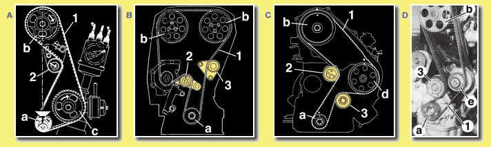
    4. The injector pump sprocket (where fitted). Figure C shows a diesel engine
  7. Slacken the tensioning pulley and rotate or move it to free the timing belt. Refer figures A, B & C above. Sometimes the water pump pulley must
    also be slackened or moved to release the timing belt. Refer figure D above
  8. Remove the timing belt
  9. Remove the tensioner and idler pulleys as necessary. Refer Figures B, C or D above

IMPORTANT: Check old belt for oil stains. Check area where belt operates for presence of oil. If any oil is present the cause of the oil leaks must first be traced. Oil seals are usually the cause of oil to leak from the engine onto the timing belt and surrounding area. Do not fit a new timing belt without correcting oil leaks.

Fitment Instructions

  1. Ensure to use the correct locking tools for the camshaft and crankshaft where applicable.
  2. Fit the new idler pulley (3) and/or the new tensioner pulley (2) in the disengaged position as necessary
  3. Fit the new timing belt (1). Ensure the “arrows” on the belt point in the correct direction and that any timing marks align with those on the sprockets
  4. Tension the belt by rotating the tensioner pulley (2) or the water pump (e) in Figure D
  5. Temporarily tighten the tensioning pulley (2) or water pump (e)
  6. Turn the engine clockwise through 2 full turns (revolutions 360°) and return it to the timing position (TDC)
  7. Check the alignment of all timing marks, timing holes (fit timing pins) and the like
  8. Fit the belt tensioner tester and check that the tension matches the recommended value. Tighten the nut of the tensioner pulley (2) and/or bolts
    of the water pump (e) to the recommended torque settings
  9. Refit the timing cover(s)
  10. Refit the crankshaft pulley and tighten this up to the recommended torque settings
  11. Refit and tension all drive belts previously removed
  12. Reconnect the battery
  13. Ensure all correct / special tools are used as specified by the vehicle manufacturer
  14. Ensure that the work is done by a reputable workshop or dealer. 16 valve and 20 valve engines are NOT advisable to work on by the DIY
    mechanic.

Fitment procedure of a new water pump

  • Find, correctly identify and repair the cause of the original WATER PUMP failure before attempting to fit a new water pump.
  • Flush and drain the cooling system completely.
  • Clean and inspect all mounting surfaces.
  • Install the water pump after applying grease lightly to both sides of the gasket.
  • After the water pump has been tightened, make sure that it moves freely by turning the shaft with your hand.
  • Do a visual inspection of the hoses, fan blades, pulley and belts to make sure that they are all in order before fitment.
  • Fill the cooling system with a mixture of water and anti-freeze / coolant and make sure that there are no leaks.
  • Check and replace the filler cap if need be.
  • Run the engine until it reaches normal operating temperature and check that there are no leaks.
  • Let the engine cool down and recheck the coolant level.

Anti-Freeze / Summer Coolant

The most commonly used additive is ethylene glycol. These products are for use in summer and winter where they provide both anti-freeze protection under cold conditions and boiling protection under high temperature conditions. The glycol in the anti-freeze also acts as a lubricant for the water pump bearings.

Recommended mixture ratios:

  • Petrol engines: 30% Anti-Freeze and 70% water.
  • Diesel engines: 50% Anti-Freeze and 50% water.

ANTI-FREEZE SHOULD BE CHANGED EVERY 12-18 MONTHS.

What creates oil pressure?

Many people think that the oil pump produces the oil pressure. Actually the pump creates the flow of the oil and the restrictions in the oil passages and bearing clearances of the engine produce the pressure.

New Oil Pump Fitment Precautions

  • The oil pump must be well primed with engine oil prior to fitment. (It is a hydraulic and not a pneumatic pump and oil will not be drawn up from the sump until it has been primed)

When fitting, make sure of the following important points:

  • Find, correctly identify and repair the cause of the original OIL PUMP failure before attempting to fit a new oil pump.
  • The oil pump is squarely seated on the engine.
  • The gasket is not damaged / new gasket fitted.
  • The oil pick-up pipe is securely fitted and is not fractured in any way. (If air is drawn into the lubrication system it will result in poor oil pressure)

Priming the oil system

In the past the installer merely spun the oil pump with a drive shaft before fitting the distributor. In many cases, this is no longer possible. To properly prime an oil system, one should use a pressure primer, which is attached to the oil gallery to pump oil through the engine lubrication system.

ALWAYS MAKE SURE THAT YOU HAVE THE CORRECT OIL PRESSURE BEFORE STARTING THE ENGINE!

Other DIY Advice

Cylinder Head Gasket Fitment Guide

  1. Ensure that cylinder head and block surfaces are clean and flat and that the surface finish meets manufacturer’s RA specifications.
  2. Check head height. If uncertain, obtain manufacturer’s specifications. Fit Payen headsaver shim (on cylinder block side) if head has been over-
    skimmed. Overskimming raises the compression ratio and causes overheating, ultimately leading to cylinder head gasket failure.
  3. Check that the correct gasket is installed. Compare against the gasket that was removed. Ensure that the locating dowel height and diameters are correct and fitted correctly.
  4. Check that all bolts, threads, washers and nuts are clean and undamaged. Do not re-use stretch bolts.
  5. Apply very light film of engine oil to under side of the head bolts, washers and threads.
  6. Torque head bolts in recommended sequence and to the manufacturer’s specification, using a correctly calibrated torque wrench and a degree bar where necessary.
  7. No Chemicals Please! Adding chemical sealants to cylinder head gaskets causes the following problems:
    1. Burning away of sealant, leading to a loss of clamp load
    2. Flow of sealant into water and oilways could block small metering holes and restrict coolant and oil flow.
    3. Solvents in adhesive could degrade gasket coating body material.
    4. Contamination, by trapping foreign particles on the gasket surface.
    5. By adding solvent, grease or chemicals will void the manufacturer’s warranty.
  8. Whenever re-torquing is necessary, first loosen each bolt by giving it a 1/4 inch turn, then re-tighten to required torque. This does not apply for angle-controlled tightening. Cylinder head gaskets settle slightly when exposed to heat and vibration. If the head bolts are not re-torqued after an initial period of engine operation, the clamping load is reduced and leakage occurs.

Symptoms of water leakage

  • Water level disappears within radiator – Low level
  • General Engine overheating due to low coolant,
  • Check for water leaks externally / Evaporation stains.
  • Water leakage on chassis / floor/
  • Water leaks into oil galleries.
  • Oil level appears to increase.

Symptoms of oil leakage

  • Reducing oil level in engine sump.
  • Visible oil leakage on engine block, cylinder head, chassis and floor.
  • Oil leakage into cooling system.
  • Oil leakage past gaskets and seal.
  • Blue smoke from exhaust.

Your engine is a mechanical entity and cannot run on its own without your care. It is heart-breaking when one sees an engine being serviced only when it breaks down. This is not what the manufacturer intended. If you don’t service your vehicle regularly, then its value will depreciate faster and it will be less reliable than it would if you serviced it. The service intervals vary from one manufacturer and model to another and also, if it is petrol or diesel powered. Generally on a petrol engine, the service intervals are either every 10,000 kms or 15,000 kms and for a diesel engine, every 5,000 or 7,500 kms. The purpose of servicing your vehicle regularly is to ensure that the oil and filters are changed and to check that nothing is going wrong (preventative maintenance). Generally there are A; B and C service intervals. The work done varies. An ‘A’ service could be a major service, where a fair amount of work is done. A ‘B’ service with a few less items done and a ‘C’ which is mainly where the essential wearing parts are replaced. These include such items as:

  • Fuel Filter
  • Oil
  • Oil filter
  • Air filter
  • Spark plugs

If cost is a criterion and you cannot afford to send your vehicle to the franchise dealer, then please choose a reputable workshop or mechanic to do the job. If you cannot afford one of these trained people and intend to do the job yourself, then here is some advice. Please bear in mind that there may be other work criteria, depending on the kilometers your vehicle has done, (such as brakes; cam belts, etc.) that the manufacturer would like carried out when servicing your vehicle.

Draining the oil

The oil in your engine is the life blood. It must be clean and does have a life span. It is mainly this life span that dictates the service intervals. When purchasing oil, look in your handbook for the correct quantity that is required and what grade of oil is required. Before draining the oil, make sure that the engine is at operating temperature. The oil is drained by taking out the drain plug, which is situated at the bottom or side of the engine sump. Do not throw the old oil down the drain!!! There will be places near you that have recycling tanks. Put it into one of these tanks. Whilst the oil is draining, unscrew the oil filter. This may be quite tight. Purchase a tool for doing this. It is like a belt with a ratchet. Leave the drain plug out for at least half an hour, so that all the oil has drained. Do not forget to put it back and tighten it to specification.

Changing the oil filter

You have now removed the old oil filter. Make sure the replacement filter you have bought is the correct part. On the new one, you will find a rubber oil seal on the face. Put oil on your finger and rub it on the face of this seal. Rather too much than too little. Screw the new filter on. Make sure it is hand tight.

DO NOT use the tool you have purchased to tighten it.

Make sure the oil drain plug is back in the sump and that it is tight. On the top of your engine is your tappet cover and in this cover is a cap. Remove this cap and pour the new oil slowly in there. Pour in the correct quantity. DO NOT overfill it. Check that the level is correct. Replace the oil filler cap.

Changing the air filter

This is a fairly simple operation. Open the air filter housing and remove the old one. Wipe the inside of the housing with a damp rag, thereby removing all the loose dust. If your air filter has a “top” it will show you. After putting in the new air filter, close the housing. Make sure you replace the air filter with the correct replacement filter.

Changing the fuel filter

Locate the filter – either in the engine compartment or close and underneath the vehicle near the fuel tank. Undo the hose clips / clamps from the inlet and outlet side of the filter. Remove the pipes. Check the rubber hoses for perishing. Replace as required. Replace the clips / clamps as required. Place new fuel filter in position. Refit the clips / clamps. Ensure minimum spillage of fuel. Check for leakage after engine has started.

Changing the spark plugs

A fairly simple operation as well. Remove the high tension from the spark plug, unscrew the plug and screw in the new one. Replace the lead. Then go onto the next plug. Plugs must be hand tight. Do not tighten them like you would tighten a bolt. Just nip them with the spanner. Do this methodically so that you don’t mix up the high tension.

  • Ensure to purchase the correct heat range and part number spark plugs for your specific vehicle.
  • Remove the high tension wire/s from the spark plug/s one by one, (if unsure mark these high tension wires).
  • Unscrew, remove and replace one spark plug at a time.
  • Ensure to hand tighten first – then torque to manufactures specification,
    Replace the spark plug lead / high tension wires. Do this methodically so that you don’t mix up the high tension wires.
  • Do the same with the next until complete.

Once all of this has been done, check that the oil drain plug is in tight. Check that the oil filter cannot be tightened any more, by using your hands. Is the oil filler cap back in the tappet cover? Is the air filter housing secure?

Once you are satisfied that all is well, start the engine. Do not rev it. The oil pressure light on the dash might take a second or two to go out, but ensure that it does. Leave it to idle for about 5 minutes. Switch the engine off. Check the oil level. You will most probably find that the level has decreased. This is because the new oil filter was dry and has taken some oil. Top the engine up with ±500ml. Make sure that there are no oil leaks. Particularly, look around the oil filter. Some other things to do would be to check:

  • Radiator coolant level. Do not take off the radiator cap. (Remove the radiator cap ONLY when the engine is cold).
  • Ensure the plastic expansion bottle is in good shape and does not leak engine coolant.
  • Check the pipe going to the radiator.
  • Check other coolant pipe on the engine for clamps and / or any damaged hoses or missing clamps.
  • Ensure the correct combination of water and anti-freeze coolant as prescribed in your handbook in filled.
  • Check the Brake and clutch fluid levels.
  • Check windscreen washer level and wiper blades.
  • Look in your handbook for the correct tyre pressures and check them, including the spare wheel. Is the tread depth legal?
  • Are the fan belts frayed or cracked? If they are, replace them immediately!!
  • Battery water. If corrosion is starting on the terminals, clean them and seal them with some grease or petroleum jelly (Vaseline).
  • Ensure that all lights are working correctly, including the brake lights and indicators.

Most petrol and diesel engines circulate enough oil to lubricate and cool all moving parts. In these conditions, plain or shell-type bearings are used (as opposed to ball and roller bearings). These bearings are light, easy to install and relatively inexpensive. They can be made cylindrical or in two halves to allow them to be fitted around crank shafts / gudgeon pins and camshafts.

The simple appearance of plain bearings belies relies in the complexity of its design, development and technology which is necessary to produce components of premium quality. “AE” – Federal-Mogul have over 90 years of experience in materials, development and technology relating to bearings.

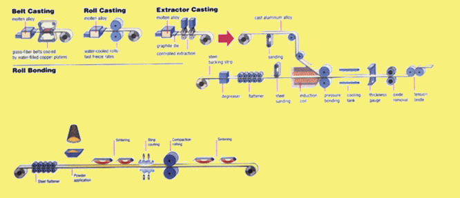
Bearing manufacturing processes include the following: alloy casting; roll bonding; annealing; powder blowing; powder spreading; compaction and sintering of copper based materials; as well as surface preparation and electroplating.

Copper-Lead Bearings
The production of engine bearings commences with the bearing material being bonded to a steel backing in the form of a long strip which is then cut, pressed and machined to its required shape. Copper-lead mixtures may be cast or sintered onto a steel backing.

AE uses the sintering process where a copper-lead powder is applied to a copper-plated steel strip. Heat is used to bond the copper-lead particles to each other, as well as to the steel backing strip.

The structure is then consolidated by pressure rolling for compaction to remove porosity. The majority of these bearings will be formed from a mixture of 30% lead and 70% copper.

After production machining, copper-lead bearings are overlay plated with a third layer, which must be strong, yet soft enough to protect the crankshaft against embedded particles or debris. This overlay plate will be between 0.013mm and 0.038mm thick, and will provide the required surface qualities. These are compatibility, conformability; embed ability and superior corrosion resistance. As a matter of interest, after much research, the main causes of bearing failure can be listed in percentages as follows:

  • Debris in engine 43%
  • Lack of lubrication 17%
  • Assembly faults 12%
  • Alignment faults 12%
  • Overload 7%
  • Corrosion 4%
  • Other 5%

At Alert Engine Parts, we specialise in engine parts. Should you have any questions or queries do not hesitate to ask us for assistance.

Disclaimer

Whilst every care has been taken to ensure the accuracy of this document, we cannot be held responsible for direct or indirect losses incurred as a result of the contents hereof. It is imperative that any assembly of, workmanship / repairs on a motor vehicle engine, be carried out by a person suitably qualified to undertake such work. NB: Our warranty does not cover part failure when such parts are fitted by anyone but an engine rebuilder or workshop recognised by RMI.